Review: overclocking of ATI RADEON 9700 PRO – Modification To The Extreme Introduction or “Catch up and overtake the GeForce FX”- At the moment, video cards based on ATI RADEON 9700 PRO remain the fastest and most modern 3D gaming cards. However, the competitor from NVIDIA, GeForce FX, has already been announced, and the appearance of video cards based on it is not far off. Aside from the prices of new video cards and the price-quality ratio of new boards, but focus on performance, then, judging by various indirect data from scattered sources, on the whole NVIDIA GeForce FX (NV30) may be about 30% more productive than the current leader, ATI RADEON 9700 PRO (R300).
ATI is already preparing a response in the form of the R350 – the “overclocked” and improved R300, but we should expect its appearance not earlier than spring 2003. Until then, to all appearances, the situation will not change in ATI’s favor – the new chip from NVIDIA will come out on top in terms of performance.
Those who have already bought an ATI RADEON 9700 PRO should not worry – the stock of functionality and performance of these video cards will last for a long time.
Especially if you try to increase performance by overclocking. The goal of our present experiment is to achieve the maximum performance increase from ATI RADEON 9700 PRO by extreme overclocking, ideally not less than 30%, so that even here and now, at least in a single copy, there is a video card capable of “catching up and overtaking” NVIDIA GeForce FX. An additional goal of the experiment, since we manage to change the frequency of the graphics core and video memory within wide limits, is to evaluate the “balance” of the ATI RADEON 9700 PRO indirectly, by evaluating the performance gain when overclocking the core and video memory under different conditions.
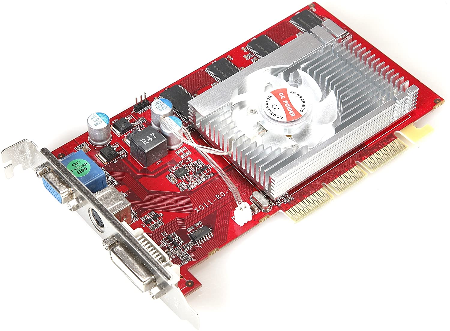
The honor of sacrificing oneself in the name of speed fell to the FIC 1stGraphics AT010 video card based on the ATI RADEON 9700 PRO, which, by the way, has already been in our test lab:

So let’s get started! ..
Cooling system installation
The first step in overclocking a video card is to take care of the effective cooling of its components. I decided to cool the video memory on the board in a passive way – with heatsinks. For each of the 8 memory chips on the ATI RADEON 9700 PRO, I had to use a separate heatsink, as there were rather high capacitors soldered between the memory chips on the board, which did not allow installing such heatsinks that would cover two chips at a time. To make small heatsinks, we had to cut the heatsinks included in the Thermaltake Memory Cooling Kit into three parts each. The heatsinks were fixed to the memory chips using pieces of adhesive thermal pad included in the same Thermaltake Memory Cooling Kit.
With that, all the troubles associated with ensuring normal heat dissipation from memory chips were over. A standard cooler installed on ATI RADEON 9700 PRO cards is not suitable for cooling the graphics core during extreme overclocking – you need to look for something more efficient. The ATI RADEON 9700 PRO chip is designed in such a way that heat is removed directly from the crystal surface. To protect the crystal from chips, a special metal frame is installed directly on the chip substrate, which eliminates distortions when installing the cooler. Having this framework can sometimes lead to a problem. The problem is that on some motherboards, the top surface of the frame protrudes a fraction of a millimeter above the plane of the crystal, preventing tight contact between the heatsink and the surface of the chip.
Fortunately, this frame, being not soldered, as I mistakenly wrote in the ATI RADEON 9700 PRO review , but glued to the substrate, is surprisingly easy to remove – you just need to carefully (!) Poke it with something thin, for example, a cutting knife blade paper.
So, remove the frame:

Now nothing prevents the installation of a normal cooling system for the graphics core.
After weighing all the pros and cons, I decided to use the Poseidon WCL-02 water cooling system from 3R System . This system suited me both in terms of size and power, but did not include a water block for graphics chips and chipsets. I had to include a domestic-made water block in the system, provided by its developer, an enthusiast of domestic water cooling systems, Vyacheslav Zaikin… This water block for graphics chips and chipsets, by the way, made entirely of pure copper, perfectly matched the Poseidon WCL-02. To secure the water block, I used a clamping bracket and two long bolts through the holes in the board. As a thermal interface – KPT-8 thermal paste.
When assembled and ready for testing, the board looks like this:


Increasing the voltage supply of the graphics core and video memory
Increasing the voltage of the graphics core : The power supply for the ATI RADEON 9700 PRO chip on the board is provided by a switching regulator with the SC1175CSW control chip from Semtech :

This microcircuit has two independent control channels, but in this case they are connected in parallel. A typical circuit for switching on a microcircuit in this mode is shown in the figure:

The output voltage of the stabilizer is set by the resistance of the resistors R1 and R12 according to the formula Vout = 1.25x (1 + R12 / R1) (numbering of resistors according to a typical connection scheme). On a typical connection diagram, it is marked in blue how by using the shunt resistor R1 ‘you can increase the voltage of the graphics core.
The nominal supply voltage of the graphics core on the board was 1.5V . After soldering a 2.7 kOhm shunt resistor to pins 18 and 20 of the microcircuit, as shown in the figure …:

… the power supply voltage of the graphics chip was 1.75V . The increase in voltage compared to the original value was 16.7% – not that much, especially when you consider that now the heat from the core is removed using a water cooling system with a copper water block. Increasing the voltage of the video memory : Next to the voltage regulator of the graphics core, under the aluminum plate designed for heat dissipation, there is a voltage regulator for the video memory microcircuits. In order to have access to the components of this stabilizer, I had to very carefully remove this plate. It is very neat
– the plate is firmly glued to the microcircuit cases with heat-conducting glue, and if you do not calculate the force, you can easily ruin the video card by tearing the microcircuits off the board.
After removing the plate, the IRU3037A microcircuit from the International Rectifier was found , which stabilizes the supply voltage of the input-output circuits of the video memory microcircuits ( VDDQ ). As with the first stabilizer, here the output voltage is set by the ratio of the resistances of the resistors in the feedback circuit, and to increase the supply voltage, it is enough just to change this ratio by soldering an additional shunt resistor.
Before the rework, the supply voltage of the input-output circuits (VDDQ) of the video memory chips was 2.78V, and after soldering a 10kΩ resistor to pins 1 and 4 of the microcircuit as shown in the figure …:

… the output voltage was 3.19V .

Due to the presence of this aluminum plate, which after reworking the board had to be installed in place, first small wires were soldered to the microcircuit terminals, and only then a resistor was soldered to them. The voltage regulator for supplying the internal circuits of the video memory chips is located in the opposite corner of the back side of the board. The stabilizer is made on the ISL6522CB chip from Intersil :

The nominal supply voltage of the internal circuits ( VDD ) of the memory microcircuits was 2.92V , but after soldering an additional 2.7kΩ resistor to pins 5 and 7 of the microcircuit, as shown in the figure …:

… it went up to 3.32V . So, the board is ready for extreme overclocking. The maximum frequencies at which the motherboard worked steadily under extreme overclocking were 450 MHz for the graphics chip and 800 (400DDR) MHz for the video memory. That is, the clock frequency of the graphics core relative to the nominal, 325 MHz, increased by 38.5% , and the frequency of the video memory relative to the nominal at 620 (310DDR) MHz – by 29% .
The stability of the motherboard during overclocking was determined by successfully passing the full set of 3DMark2001 SE tests at a resolution of 1024x768x32, and immediately after that – four benchmarks in Unreal Tournament 2003 at resolutions 800×600, 1024×768, 1280×1024 and 1600×1200 with the default graphics quality settings …
Before increasing the supply voltage and installing additional cooling, the maximum frequencies at which the video card worked stably were 380/750 (375DDR) MHz . Thus, if the increase in the core supply voltage led to a serious increase in the overclocking potential, from 380 to 450 MHz, then the video memory with an increase in the supply voltage began to “chase” a little higher – from 750 to 800 MHz. Perhaps the upper limit of the video memory frequency is limited by the layout of the board, although it is possible that I got a copy of a video card with already excellent “overclocked” memory, and the increase in the supply voltage did not play a big role. However, all this is not as interesting as testing an overclocked video card itself. Before starting testing, it is worth describing the test system and testing conditions.
Test system and test conditions
Having assembled the test system, I could not help but take a couple of shots of the “extreme overclocker’s workplace”:


The view of a test system with an installed video card, a water cooling system for its graphics core and additional fans blowing over the video memory chips is scary, but what won’t you do for the sake of speed? :). Test system configuration:
FIC 1stGraphics AT010 based on ATI RADEON 9700 PRO;
Processor – Intel Pentium4 2800 MHz;
Motherboard – ASUS P4S8X (SIS 648);
Memory – 512 MB DDR SDRAM PC 2100 Samsung CL2.5;
Hard drive – IBM DTLA 305030.
software:
Windows XP Professional
DirectX8;
Driver 6200 (Catalyst 4.3) for Windows XP for video cards based on ATI chips;
Unreal Tournament 2003 v.2107.
Extreme overclocking and testing were carried out indoors at a temperature of 20-25 degrees Celsius. The tests were carried out in Unreal Tournament 2003 at resolutions from 1024×768 to 1600×1200 in four modes: with the default graphics quality settings, with forcing anisotropic filtering, forcing full-screen anti-aliasing, and when these functions are enabled together.
Speed in 3D
To assess the effect of overclocking the graphics core and video memory, I chose 2 intermediate values of the core and video memory frequencies, so that the interval between frequencies was approximately uniform. As a result, we got 16 options for combining core and video memory frequencies. For the convenience of perception and evaluation of the efficiency of overclocking the core and video memory, the test results in each of the modes have been compiled into 2 graphs.
One of them shows the results of testing the board at a fixed core frequency and with a changing video memory frequency. This graph shows the “usefulness” of overclocking the video memory. The second graph shows the lines formed by the results at a fixed video memory frequency and a changing core frequency; the slope of the lines in this graph shows the efficiency of overclocking the graphics core.
In order not to clutter up the graphs, I have given the numerical values of the results in a separate table for each test. Unreal Tournament 2003, default graphics quality settings :


According to the test results, it is obvious that overclocking a video card in 1024×768 mode is practically useless, but with an increase in resolution, the performance gain appears and becomes very noticeable.
Judging by the results, the performance gain when overclocking the graphics core in this test leads to approximately the same performance gain as overclocking the video memory.
This means that, at least for Unreal Tournament 2003 with the default settings, the architecture of the ATI RADEON 9700 PRO is perfectly balanced. For a more accurate assessment of the performance gain during overclocking, you can provide graphs that show the performance gain during overclocking as a percentage relative to the results of the board at nominal frequencies:


These graphs confirm the previous ones: the performance gain during overclocking barely exceeds 5% at 1024×768, but with increasing resolution, when the limiting effect of the central processor decreases, it increases to 20-25% in 1280×1024 and 30-35% in 1600×1200.
Judging by the shape of the lines reflecting the test results at 1600×1200, we can conclude that the core overclocking turned out to be a little more efficient. However, do not forget that the frequency of the graphics core during extreme overclocking “grew” by almost 40%, while the frequency of the video memory – by 30%. That is, in fact, the effect of overclocking the graphics core and video memory turned out to be approximately the same, that is, the ATI RADEON 9700 PRO proved to be perfectly balanced in this situation. Numerical values of test results:

Unreal Tournament 2003, forcing fullscreen anti-aliasing:


Forcing the highest level of full-screen anti-aliasing, 6x, increases the load on the video card dramatically, and overclocking is beneficial at all tested resolutions.
From the look of the graphs, we can conclude that when forcing full-screen anti-aliasing, the performance gain with overclocking the graphics core and video memory is approximately the same. That is, even with full-screen anti-aliasing, the ATI RADEON 9700 PRO behaves like a perfectly balanced video card in Unreal Tournament 2003. Numerical values of test results:

Unreal Tournament 2003, forcing anisotropic filtering:


With 16x Quality anisotropic filtering enabled, ATI RADEON 9700 RPO uses much more texture samples to calculate texture color than bilinear and trilinear filtering – up to 128 instead of 4 or 8. This means that much more is required to calculate the color of each pixel with anisotropic filtering data from textures, that is, the load on the memory bus – texture data is transferred over the memory bus – should increase significantly.
Therefore, overclocking the video memory should seriously increase the performance with anisotropic filtering. However, judging by the test results during overclocking, a much larger performance gain was provided by overclocking the graphics core. This means that the texture caching system in the ATI RADEON 9700 PRO is perfectly tuned to work with anisotropic filtering, and when this function is forced, the load on the video memory practically does not increase – all texture data are taken from the caches.
The main “inhibiting” factor in this case is the significantly increased volume of additional calculations associated with averaging the colors of a large number of texture samples; these calculations are exactly what the texture units of the graphics chip are doing. Do not forget that texture caches are located in the graphics core and operate at its frequency. As a result, overclocking the graphics chip with anisotropic filtering turned out to be much more effective than overclocking the video memory. associated with averaging the colors of a large number of texture samples, these calculations are exactly what the texture units of the graphics chip are doing.
Do not forget that texture caches are located in the graphics core and operate at its frequency. As a result, overclocking the graphics chip with anisotropic filtering turned out to be much more effective than overclocking the video memory. associated with averaging the colors of a large number of texture samples, these calculations are exactly what the texture units of the graphics chip are doing. Do not forget that texture caches are located in the graphics core and operate at its frequency. As a result, overclocking the graphics chip with anisotropic filtering turned out to be much more effective than overclocking the video memory.
The “imbalance” of the ATI RADEON 9700 PRO when using anisotropic filtering is obvious. Numerical values of test results:

Unreal Tournament 2003, forcing anisotropic filtering and full-screen anti-aliasing:


When forcing full-screen anti-aliasing and anisotropic filtering, the overclocking of the graphics core on the ATI RADEON 9700 PRO turns out to be more efficient, and this is the fault of the anisotropic filtering, which loads the graphics core much more than video memory.
In the “hardest” mode, when the load on the video card is great and the central processor does not limit the results of the ATI RADEON 9700 PRO, the performance gain during overclocking should be the highest. The graphs of the percentage increase in productivity confirm this:


These graphs also clearly show that under maximum load – with forcing anisotropic filtering and antialiasing – the overclocking efficiency of the ATI RADEON 9700 PRO graphics core turned out to be much higher than the video memory overclocking efficiency.
The performance gain under extreme overclocking turned out to be noticeable – 30-35% – according to preliminary data, this is exactly what ATI RADEON 9700 PRO needs to “catch up and overtake” NVIDIA GeForce FX :). Numerical values of test results

Conclusion
So, extreme overclocking of ATI RADEON 9700 PRO, despite all the fears, is clearly not a hopeless business.
While ensuring adequate cooling and increasing the voltage of the graphics core and video memory, I managed to raise the frequencies of the graphics core and video memory by 38.5% and 29%, respectively. The maximum frequencies, at which the board worked steadily, amounted to 450/800 (400DDR) MHz, which can be safely called a record :).
The performance gain with this overclocking, judging by the test results in Unreal Tournament 2003, amounted to 30-35%, that is, it turned out to be adequate to the increase in the clock frequencies of the graphics core and video memory.
.
The question about the poor “balance” of the ATI RADEON 9700 PRO, which has been raised more than once in reviews, has real grounds for concern. With a 256-bit DDR SDRAM bus, the ATI RADEON 9700 PRO has “only” 8 texture modules, and the texturing speed in some cases may be a factor limiting the motherboard’s performance. However, as the tests showed during overclocking, the ATI RADEON 9700 PRO becomes obviously “unbalanced” only when anisotropic filtering is applied, in all other cases the load on the graphics core and the memory bus is evenly distributed. Well, we are ready for the NV30. And you? 🙂 Note :
This material is a kind of experiment; it is by no means a call for extreme overclocking or re-soldering of video cards;
Such modification of the board will shorten its service life;
Any modification to the board will automatically void the user’s warranty;
In the event of a failure of a video card or other components as a result of its modification, all responsibility lies with the user.
Related posts:
 Bitmain Antminer r4 Review – Benefits Profitability Payback Specification
  Nvidia GTX 1080 ti Hashrate – Review | Overclocking |Ethereum |Profit (sky high)
  Antminer S5 ASIC Hashrate – Review Profitability Payback Period
  Asic Antminer S1 Hashrate – Review | Test| Specs| Pros & Cons | Set-up|
  Miner Baikal Giant x11 – Hashrate|Profitability| Specs
  Radeon Hd 7970 Hashrate -Review|Profitability | Specs | Pros and Cons